


Beyond 3D: Automating Substation Engineering
By Ebazer Khairetdinov
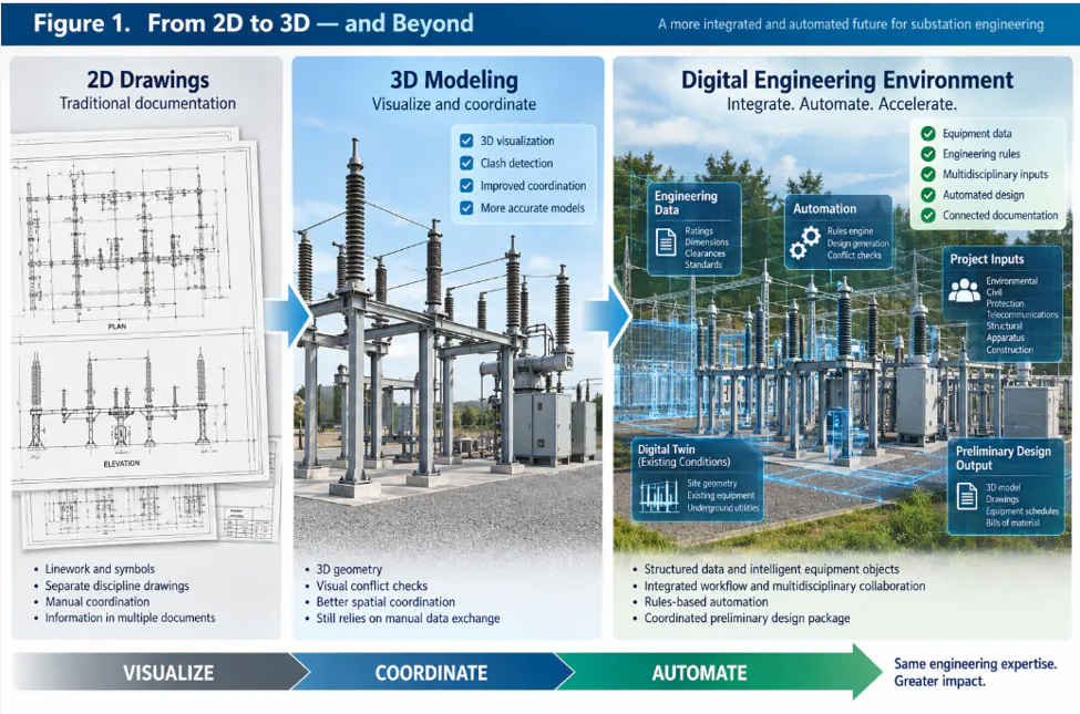
The electric power industry has made significant progress in moving substation engineering from two-dimensional drawings toward three-dimensional digital design. Modern 3D tools allow engineers to visualize equipment arrangements, identify physical conflicts, coordinate structures, and develop more accurate models of new and existing facilities.
But 3D modeling alone does not fundamentally change the engineering process.
On many utility projects, the model remains primarily a digital representation of a design developed through a largely conventional workflow. Project managers, substation engineers, civil engineers, protection engineers, transmission engineers, telecommunications specialists, structural engineers, apparatus engineers, and construction teams still exchange large amounts of information through drawings, spreadsheets, reports, emails, meeting minutes, and separate engineering systems.
The next step should therefore go beyond creating better 3D models.
A more ambitious approach is to create an integrated digital engineering environment in which standardized equipment models, utility standards, multidisciplinary engineering inputs, existing facility data, and rules-based automation work together to generate a substantial portion of a preliminary substation design.
The objective is not to remove engineers from the process. It is to automate repetitive and rules-based engineering tasks so engineers can devote more time to technical judgment, complex project constraints, interdisciplinary coordination, constructability, and design verification.
From 3D Models to Engineering Objects
The foundation of such a system would be a standardized digital equipment library.
Utilities typically rely on approved families of circuit breakers, disconnect switches, transformers, instrument transformers, capacitor banks, relay racks, batteries, chargers, AC and DC panels, structural components, insulators, conductors, grounding materials, and other equipment.
A conventional 3D library may represent the physical geometry of these components. An automated engineering environment would need to go further.
Each component would become a data-rich engineering object.
A circuit breaker object, for example, could contain its physical dimensions and weight, electrical ratings, short-circuit duty capability, bushing current transformer ratios, connection points, required electrical and maintenance clearances, associated foundations and structures, manufacturer information, and related elementary and wiring diagrams.
The same principle could extend throughout the substation.
In other words, the digital model would evolve from:
Equipment → Geometry
to:
Equipment → Geometry + Engineering Data + Interfaces + Applicable Rules + Documentation
Once equipment is represented as structured engineering data rather than geometry alone, automation becomes much more practical. This is the core of the proposed equipment-library concept: physical models are linked to the technical information engineers already use to select, place, connect, and document equipment.
Brownfield Substations: The Harder Problem
Greenfield substations provide the easiest environment for automation, but a large portion of utility engineering involves modifying facilities that have operated for decades.
For these projects, an automated system would require a sufficiently detailed digital representation of the existing facility, including both above-grade and below-grade infrastructure.
Existing buses, structures, equipment, buildings, fences, roads, foundations, conduits, and grounding systems can all constrain a new design. So can energized equipment, limited outage opportunities, underground congestion, construction access, temporary configurations, and sequencing requirements.
A technically valid arrangement on an empty digital site may therefore be impossible to construct inside an operating substation.
Brownfield automation cannot simply be an equipment-placement algorithm. It must understand the physical constraints of the existing facility.
A 220-kV Example
Consider a hypothetical 220-kV switching substation with a double-bus, double-breaker configuration and four existing transmission-line positions.
A new 220-kV generation-tie line from a solar facility must be interconnected.
A site investigation determines that the existing positions cannot accommodate another line. The property boundary leaves insufficient space for conventional expansion, while aging structural elements cannot reasonably be extended to support the new arrangement.
Preliminary engineering therefore identifies a different solution: construct a new section of 220-kV switchyard adjacent to the existing facility, transfer the existing lines, and connect the new generation-tie line.
The physical arrangement is only one part of this solution. Environmental and property constraints, grading, line entrances, protection requirements, telecommunications, equipment selection, structures, construction sequencing, outages, and procurement all affect the resulting design.
This is where an integrated engineering environment could change the workflow.
Turning Multidisciplinary Requirements Into Structured Data
The process would begin with the project objective.
A project manager or sponsor could initiate the project within the digital engineering application, defining the required scope, target completion date, interconnection information, site location, and other strategic requirements. The application would then create the initial project record and route the relevant information to the Substation Responsible Engineer. The Substation Responsible Engineer would establish the preliminary engineering basis using existing records, site investigations, and available project information.
Based on the project type, voltage level, complexity, and scope, the application could then identify the engineering disciplines whose input is required and generate the corresponding workflow. Rather than relying primarily on separate emails and manually coordinated requests, each discipline would interact with the project through the same application. Engineers could enter structured requirements, select applicable options, attach supporting drawings or studies, and identify constraints or unresolved issues. As required inputs are completed, the application could automatically notify downstream or dependent engineering groups that the information needed for their work is available.
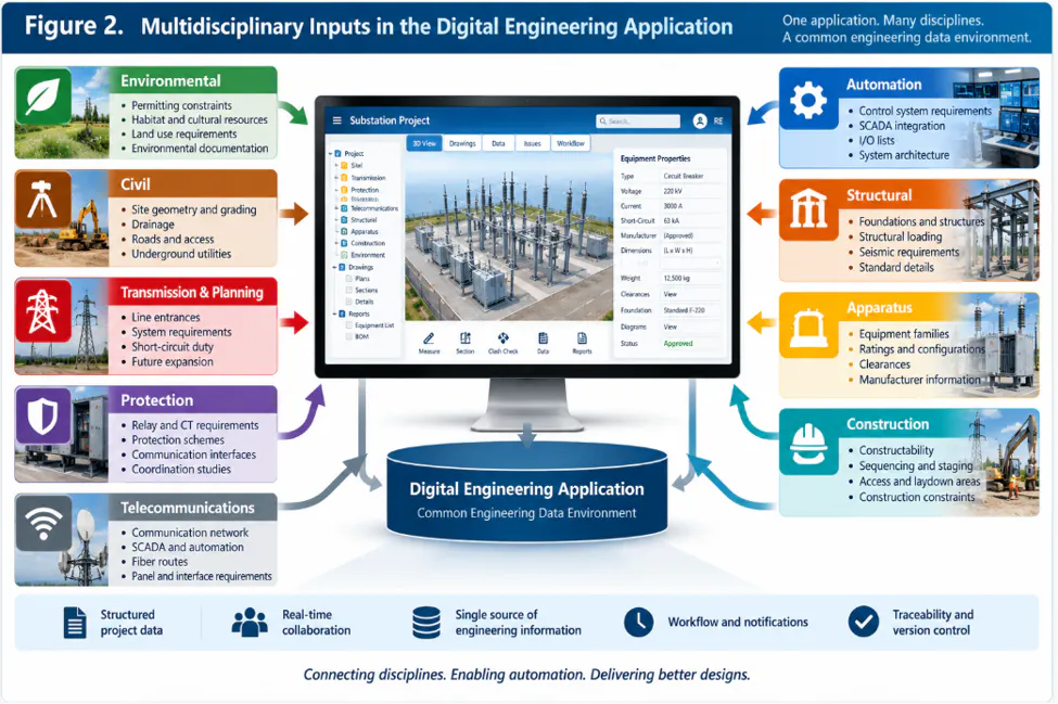
For a major 220-kV expansion, environmental specialists might define property and permitting constraints. Civil engineering could provide site geometry, grading, drainage, roads, and access requirements. Transmission engineering and planning could establish line entrances, system requirements, and short-circuit duty. Protection engineering could provide relay and current-transformer requirements, while telecommunications and automation groups define communication and control interfaces.
Structural engineering could identify applicable foundations and structures. Apparatus engineering could validate equipment families and ratings. Construction personnel could contribute constructability, sequencing, access, and schedule constraints.
The workflow would not necessarily follow a single linear sequence. Some engineering activities could proceed in parallel, while others would begin only after specific upstream requirements have been established. The application would manage these dependencies, track the status of required inputs, and route notifications or requests to the appropriate engineering groups as the project progresses.
The important change is that engineers would no longer simply exchange project information through disconnected emails, meeting minutes, spreadsheets, drawings, and separate databases. They would contribute to a common engineering data environment through a shared engineering application, where project requirements, supporting documents, discipline inputs, dependencies, and their current status are maintained as structured project data. This structured information would then become the input to the engineering rules and automation layers described in the following sections.
The Engineering Rules Layer
Structured data alone cannot generate a design. Between project inputs and engineering outputs must be a validated engineering rules layer.
This layer would contain utility design practices, approved equipment applications, standard configurations, physical and electrical clearances, structural associations, grounding requirements, and other repeatable engineering rules, together with applicable codes and standards.
Once the required project inputs have been entered, validated, and made available through the digital engineering application, the automation engine could evaluate those structured requirements against the approved digital equipment library and applicable engineering rules.
For example, suppose transmission planning establishes the required short-circuit duty, protection engineering defines current-transformer requirements, and the project configuration calls for a particular class of 220-kV circuit breaker.
Instead of repeatedly transferring these requirements among specifications, drawings, and equipment lists, the automation engine could identify compatible equipment from the approved library and associate it with the appropriate structures, foundations, connections, and standard details.
The same principle applies to physical arrangements. The automation engine could evaluate equipment geometry against validated clearance requirements and identify conflicts before a preliminary design reaches detailed engineering. The application would therefore serve as the interface through which engineers provide and review project information, while the rules and automation layers would process that structured information to support engineering design.
The software is not being asked to invent engineering requirements. It is applying requirements that qualified engineers and utility standards have already established.
That distinction is fundamental:
Automation should execute validated rules. Engineers should resolve engineering judgment.
From Inputs to a Preliminary Design
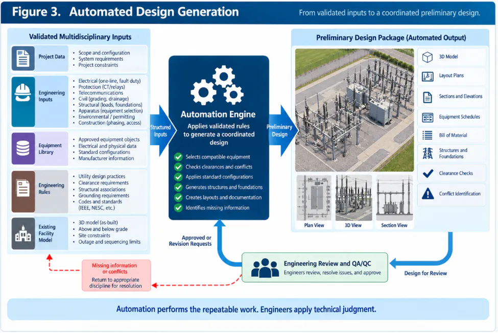
As multidisciplinary inputs are completed, the application could track their status and determine whether the information required for preliminary design has reached an appropriate level of maturity. Once the required inputs and dependencies are satisfied, the project could move from the multidisciplinary input stage into the automated preliminary-design stage. The automation engine could then combine the structured project requirements with the approved equipment library, engineering rules, existing-facility model, and applicable standard design information to generate a preliminary engineering package.
Depending on the utility's design environment, that package might include a coordinated 3D model, preliminary physical layouts, plans and sections, equipment schedules, preliminary bills of material, associated structures and foundations, and automated clearance or consistency checks.
The application could also identify missing information, unresolved dependencies, or conflicts that prevent portions of the design from being completed. Rather than forcing a result, those issues could be routed back to the appropriate engineer or discipline for resolution.
The first generated design would not become an issued-for-construction package. Instead, automation would perform much of the repeatable work required to convert established engineering requirements into a coordinated preliminary design.
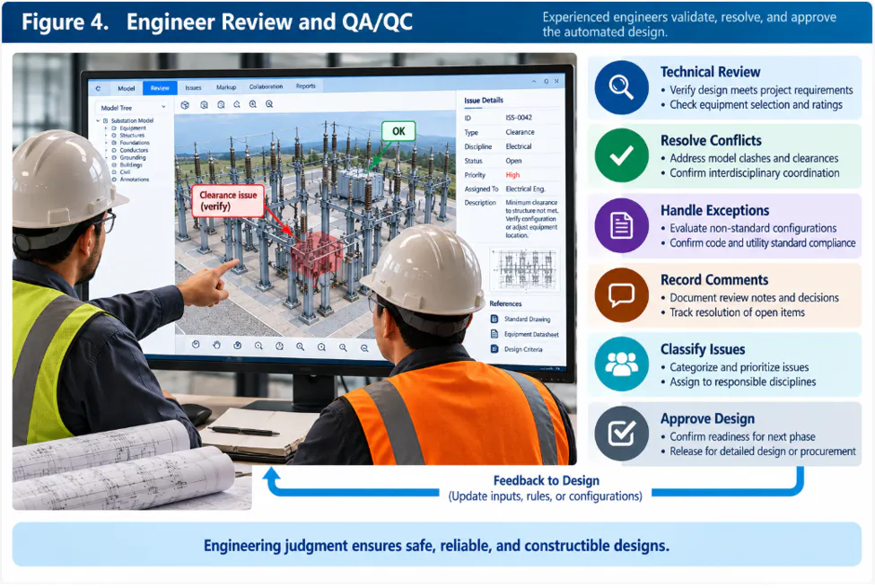
The resulting package would then be returned through the engineering workflow to the Responsible Engineer and applicable discipline engineers for technical review.
The Engineer Remains in the Loop
Substations are not manufactured on identical production lines. Even highly standardized utilities operate facilities constructed over many decades, under different standards and with different system requirements.
There will always be exceptions.
For that reason, the Responsible Engineer and applicable discipline engineers would remain responsible for reviewing the generated design, resolving interdisciplinary conflicts, evaluating nonstandard conditions, and approving the technical solution. Review comments, required revisions, and unresolved engineering issues could be recorded within the same application and routed back to the appropriate discipline or automation workflow.
Automation would also change how experienced designers use their time. Rather than repeatedly creating standard arrangements and manually transferring information between drawings and material lists, they could focus more heavily on design verification, constructability, unusual field conditions, and exception handling.
The objective is not engineer replacement.
It is engineering leverage.
Learning From QA/QC
Automated design also creates an opportunity to improve the system over time.
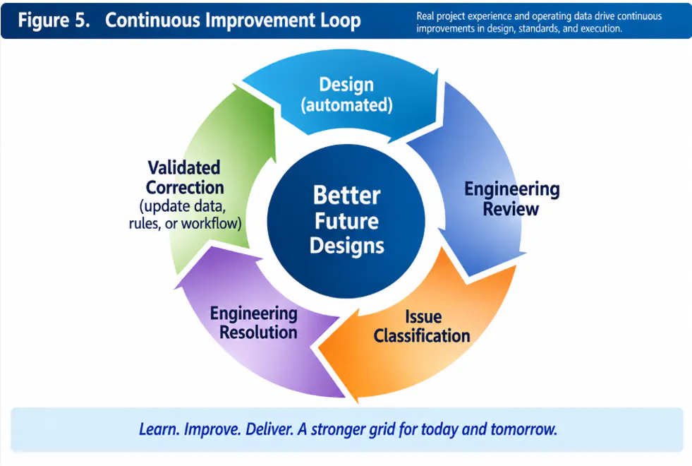
Every generated package would continue through established engineering review and QA/QC. When reviewers identify an issue, its source could be classified.
Was a project input incorrect? Was an equipment object missing information? Was a design rule incomplete? Was the existing-condition model inaccurate? Or was the project simply an exception requiring engineering judgment?
Once validated by qualified personnel, corrections could be incorporated into the appropriate data object, rule, or workflow. Because the review history, project inputs, generated outputs, and engineering comments would be maintained within the digital environment, the system could also preserve traceability between an identified issue, its technical resolution, and any resulting change to a standardized rule or engineering object.
The process becomes:
Design → Engineering Review → Issue Classification → Engineering Resolution → Validated Correction → Improved Future Designs
This controlled feedback loop is more appropriate for critical infrastructure than allowing an unconstrained machine-learning system to modify engineering rules automatically. It preserves the original concept of using QA/QC findings to improve subsequent designs while keeping engineering validation between the identified problem and any change to the governing rules.
Where AI Fits
Artificial intelligence could support specific functions within this digital engineering environment, but it should not be confused with the engineering rules or automation engines.
AI-assisted tools could help search large standards libraries, interpret legacy documents, compare drawings, classify QA/QC comments, identify similar historical projects, and flag inconsistencies among project records.
Rules-based automation, by contrast, should perform engineering actions that must be deterministic and traceable to approved requirements.
This creates a practical division:
AI helps engineers find and interpret information. Rules-based automation executes validated engineering logic. Qualified engineers retain technical judgment and approval.
Why It Matters
The benefit of this approach is not simply faster drafting.
A common digital engineering environment could reduce repeated data entry, improve multidisciplinary coordination, identify conflicts earlier, connect equipment selection directly to design outputs, and make engineering requirements more traceable throughout a project.
It could also transform existing utility standards, approved equipment, and repeatable engineering practices from reference information into active components of the design process.
These capabilities become increasingly valuable as utilities face growing demands for transmission expansion, renewable-generation interconnections, aging infrastructure replacement, transportation electrification, industrial development, and large new electrical loads.
Engineering automation will not eliminate permitting, equipment lead times, outages, construction constraints, or commissioning requirements. But it can reduce the repetitive engineering effort required to convert project requirements into coordinated designs.
Beyond 3D
The transition from 2D drafting to 3D modeling changed how substations are visualized and coordinated. The next transition could change how they are engineered.
The 3D model can become one component of a larger digital engineering environment where multidisciplinary requirements, intelligent equipment objects, engineering rules, and automated workflows work together to support preliminary design.
Such a system would not eliminate the Responsible Engineer, discipline engineers, or experienced designers. Instead, it would allow them to focus more of their expertise on complex constraints, exceptions, constructability, interdisciplinary decisions, risk, and final technical responsibility.
The future of substation engineering may therefore be less about teaching software to replace engineers and more about encoding what can be standardized so engineers can concentrate on what cannot.